


 English
 中文简体
Introduction: The Driver Board Behind Every Fine Mist
A piezoelectric atomizer disc looks simple: a thin ceramic element bonded to a metal mesh, vibrating at high frequency to push liquid through microscopic openings. The disc cannot do this job alone. It needs an electronic driver that generates the right waveform, matches the electrical load, and keeps output steady as temperature, humidity, and battery voltage change. That driver lives on a custom printed circuit board designed around the specific disc and the device enclosure.
In medical nebulizers, the stakes are higher than in consumer humidifiers. Droplet size influences how much medicine reaches the lungs, and a driver that drifts outside its operating window can change output without any obvious warning. Experienced engineers therefore treat the board as part of the therapeutic system rather than a simple container for components.
A standard off-the-shelf board is designed for average conditions. A medical atomizer must perform reliably under the worst conditions it is likely to meet in real use, including cold rooms, warm bathrooms, long overnight sessions, and rough handling during transport.
This guide explains what separates a dependable custom board from a generic one, which technical requirements matter most for medical use, how reliability testing is structured, and how a typical development project moves from specification to production. The goal is practical: to help procurement staff and research teams ask better questions and make sound decisions earlier in the project.
Standard Boards Versus Custom Boards
Many teams begin with a reference design or a general-purpose driver module, hoping that it can be adapted with minor changes. This approach works for early prototypes, but it often breaks down when the device moves toward certification and volume production. The differences are rarely visible on a bench under ideal conditions. They appear when the device is tested across its full environmental range.
| Aspect | Generic Board | Custom Board |
|---|---|---|
| Drive frequency | Fixed or loosely tuned | Tuned to the disc resonance behavior |
| Thermal drift | Output moves with temperature | Compensated across the operating range |
| EMC margin | Often marginal | Built in through layout and filtering |
| Load matching | Average load assumed | Matched to the actual disc impedance |
| Validation | Basic functional check | Environmental and life testing |
A custom approach begins with the disc itself. Its electrical behavior changes with mass loading, temperature, and liquid contact, so the driver must be designed around measured characteristics rather than nominal datasheet values. This is the main reason why a custom layout can deliver more consistent droplet output across production lots.
- Custom boards align the driver with the disc, which reduces wasted power and heat.
- Custom layouts allow tighter control over noise paths, improving electromagnetic performance.
- Custom enclosures and connectors can be planned together with the board, simplifying assembly.
Key Technical Requirements for Medical-Grade Boards
Medical programs usually define requirements in several categories at once. Electrical performance is only one part of the picture. Materials, documentation, manufacturability, and long-term stability all influence whether a design can move through a regulated development process without repeated redesign.
Frequency and Impedance Matching
The driver must produce a stable output within the frequency band that the disc needs to atomize efficiently. If the match is poor, the device may draw more current, overheat, or produce uneven mist. Good designs include margin for disc-to-disc variation, so that a slightly different transducer still operates within its target window.
Thermal Stability
Temperature affects both the ceramic element and the electronic components. A well-designed board tracks these changes so that output remains within an acceptable band. Engineers typically evaluate thermal behavior at both ends of the expected range and check that protective functions respond correctly under sustained load.
Electromagnetic Compatibility
A driver that switches at high frequency can generate noise that affects nearby sensors, wireless modules, or other electronics in the same housing. Layout discipline, filtering, grounding strategy, and shielding decisions all contribute to meeting electromagnetic compatibility targets. Addressing these issues early is far less costly than correcting them after an enclosure has been finalized.
Materials and Lead-Free Assembly
Medical programs increasingly require lead-free soldering processes and documented material compliance. Base laminates, solder mask, conformal coatings, and connectors should all be selected with traceability in mind. Suppliers should be able to provide material declarations that match the bill of materials.
- Define the disc specification, supply voltage, and channel count at the start.
- Set environmental targets for temperature, humidity, and mechanical shock.
- Specify materials and assembly processes that match regional rules.
- Plan test points so that production checks can be performed quickly.
Architecture of a Piezo Atomizer Driver
Most piezo atomizer drivers can be understood as a chain of three functional stages. The control stage decides when to run, at what frequency, and at what power level. The driver stage converts logic signals into a high-amplitude waveform that the disc can respond to. The transducer stage is the disc itself, which converts electrical energy into mechanical vibration and, ultimately, into a fine mist.
The interface between these stages deserves special attention. Signal integrity between the control stage and the driver stage affects timing accuracy, while the connection to the disc determines how efficiently energy is transferred. A custom layout keeps these paths short and controlled, which reduces losses and simplifies troubleshooting.
- Control logic should be isolated from high-amplitude switching paths.
- Feedback sensing, when used, should be placed away from noisy traces.
- Protection circuits should respond to overcurrent and abnormal load conditions.
Many modern designs also include optional features such as timed operation, multi-channel control, and sensing functions. Each added function increases complexity, so it should be justified by a clear user or regulatory need rather than added by default.
Reliability and Environmental Testing
Reliability is built through a structured test program rather than a single final inspection. A typical program moves from functional verification to environmental stress and then to extended operation. Each stage answers a different question: whether the board works, whether it survives harsh conditions, and whether performance stays stable over time.
| Test | Typical Purpose | Typical Condition |
|---|---|---|
| Temperature cycling | Solder and component fatigue | Repeated transitions between low and high temperatures |
| Humidity exposure | Corrosion and leakage risk | Elevated humidity at a moderate temperature |
| Mechanical shock | Connector and joint integrity | Controlled drop or impact pulses |
| Long-run aging | Output drift over time | Continuous operation over extended hours |
Results from these tests guide design revisions. In one anonymized program for a portable nebulizer, early builds showed a high number of field returns caused by intermittent output after repeated temperature changes. The root cause was a combination of thermal stress on solder joints and insufficient support for a heavy connector. After a layout revision and a change in component placement, the return rate dropped substantially in the following production run.
The chart above is based on the anonymized example described earlier and is intended to show direction rather than a universal benchmark. Actual results depend on the disc, enclosure, and use conditions, so teams should define their own acceptance criteria before testing begins.
Compliance and Documentation Packages
Medical device teams rarely need only a working board. They also need evidence that the board was designed and produced under a controlled system. Documentation requirements vary by market, but most programs expect a consistent set of records that can be reviewed during audits and submissions.
- Quality management system records aligned with recognized medical device standards.
- Risk management files that link electrical hazards to design controls.
- Material declarations covering restricted substances in the board and components.
- Electromagnetic compatibility test reports for the final assembly configuration.
- Traceability records that connect production lots to component batches.
Documentation should be requested early, not at the end of a project. A supplier that can explain its record-keeping process, change control method, and test procedures usually reduces friction later. It is also useful to confirm which documents are provided automatically and which require a separate agreement.
Why Change Control Matters
Even a small change, such as switching a capacitor vendor or adjusting a solder profile, can affect output behavior. Clear change notification rules protect both sides. Engineers should know in advance which changes trigger retesting and which can be accepted with a documented justification.
From Specification to Production
A well-run development project follows a predictable sequence. Each stage has its own deliverables and decision points, and skipping a stage often creates expensive rework. The process below reflects a common approach for medical driver boards, although schedules vary with complexity and regulatory needs.
- Requirement review: confirm disc specification, supply voltage, channel count, enclosure limits, and target markets.
- Schematic and layout design: produce circuit architecture and board layout with test access in mind.
- Prototype build: assemble sample boards and verify basic function with the actual disc.
- Performance and environmental testing: measure output stability, temperature behavior, and electromagnetic results.
- Design revision: adjust component values, layout, or assembly process based on test data.
- Pilot run and production: release documentation, run controlled production, and perform final inspection.
Prototype quantity matters more than many teams expect. A small batch allows engineers to observe variation between boards, which is essential for setting production tolerances. Testing only one sample can hide problems that appear when the device is assembled at scale.
Choosing a Partner for Custom Board Projects
Selecting a supplier is as important as selecting a component. The best partners combine electronics expertise with manufacturing discipline and clear communication. They ask detailed questions before quoting, explain trade-offs openly, and document decisions so that the project remains traceable.
Teams planning a dedicated piezo driver board project for a nebulizer should evaluate several areas before committing to a development schedule.
- Experience with piezoelectric loads and high-frequency driver design.
- Access to measurement tools such as impedance analyzers and inspection equipment.
- Willingness to share test methods and sample data for review.
- Capability to support both prototype and volume production with consistent quality.
- Clear communication on lead times, change control, and documentation delivery.
Questions to Ask Before Signing
A short list of questions can reveal a great deal. How does the supplier handle design changes after prototype approval? What test data is included with each shipment? How are component shortages managed? Which parts of the design are considered critical and how are they controlled? Answers to these questions show whether a supplier thinks about the full product lifecycle or only about the first build.
Frequently Asked Questions
Q1: What makes a custom printed circuit board different for a medical piezo atomizer disc?
A custom board is designed around the specific disc, enclosure, and use environment. This allows the driver to match the load, control heat, manage electromagnetic noise, and maintain stable output across the required temperature and humidity range.
Q2: How many channels should a nebulizer driver board support?
The channel count depends on the number of discs, the intended therapy, and the device design. Some products use a single channel for simple operation, while others use multiple channels for larger output or independent control. The decision should be based on measured output needs rather than assumptions.
Q3: Is a prototype run necessary before a production order?
A prototype run is strongly recommended. It reveals how the board behaves with real discs, enclosures, and assembly tolerances. Issues found at this stage are far less costly to correct than problems discovered after volume production has started.
Q4: What documents should a medical device team request from a board supplier?
Teams should request material declarations, electromagnetic compatibility reports, traceability records, change control procedures, and quality system documentation. The exact list depends on the target market and the regulatory pathway of the final device.
Q5: How long does a typical custom board project take?
Timelines vary with complexity, testing scope, and component availability. A simple driver may move from specification to prototype in several weeks, while a program with extensive environmental testing and documentation may require several months before production release.
Conclusion: Designing for Consistent Mist
For medical piezo atomizers, the circuit board is not a passive part of the device. It determines how efficiently the disc operates, how stable the output remains across conditions, and how well the final product holds up over its service life. A thoughtful custom approach turns these requirements into measurable design targets that can be tested and verified.
Engineering teams that define their requirements clearly, plan a structured test program, and choose partners with transparent processes are far more likely to reach stable production with fewer surprises.
If your team is evaluating options, a practical first step is to prepare a short requirement sheet covering disc specification, supply voltage, channel count, enclosure dimensions, and target market certifications. Sharing this information early allows a technical review that can clarify feasibility, schedule, and the testing path before any commitment is made.
Related Products
-
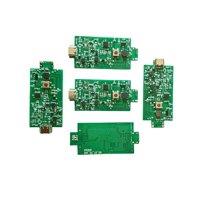
Humidifier Aromatherapy Humidifier Misting Tray PCB Board USB6V12V24V Five Head PCB Driver Board 10 Head Driver Board
-
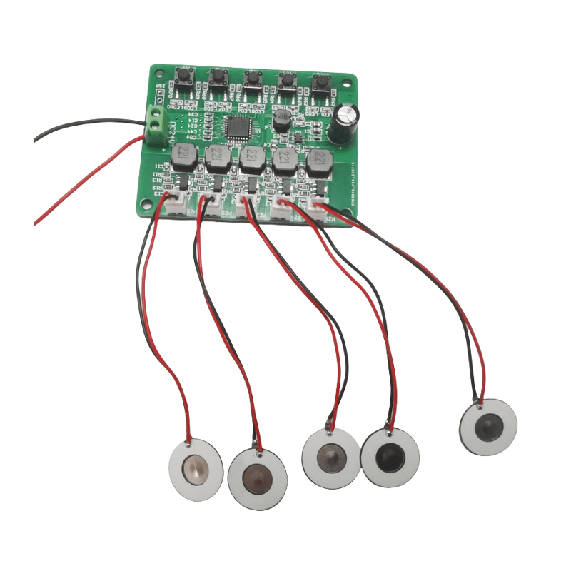
Medical Inhalation Nebulizer Respirator Head-mounted Nebulizer PCB Driver B
-
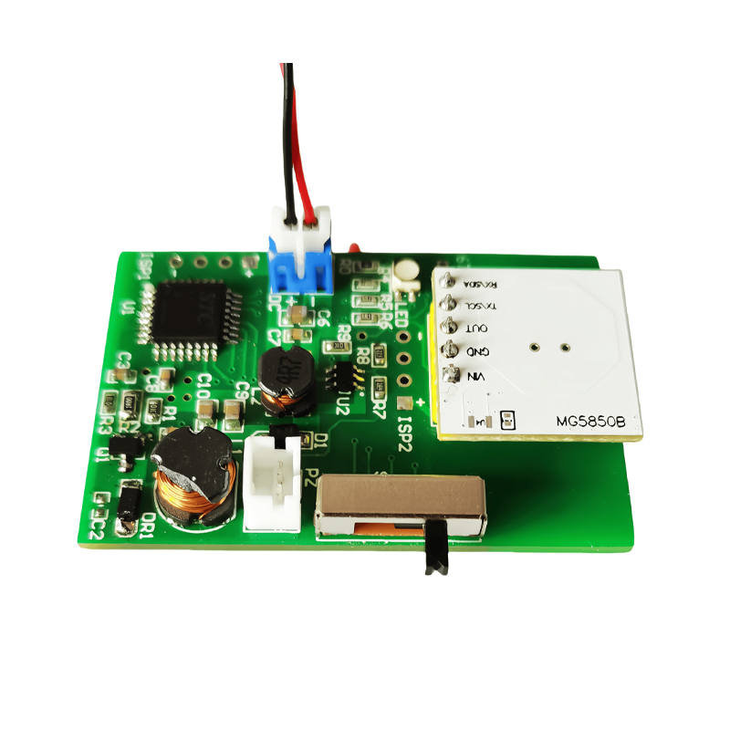
Medical Mesh Atomizer Tray PCB Electronic Smoking Cessation Atomizer PCB Driver Board
-
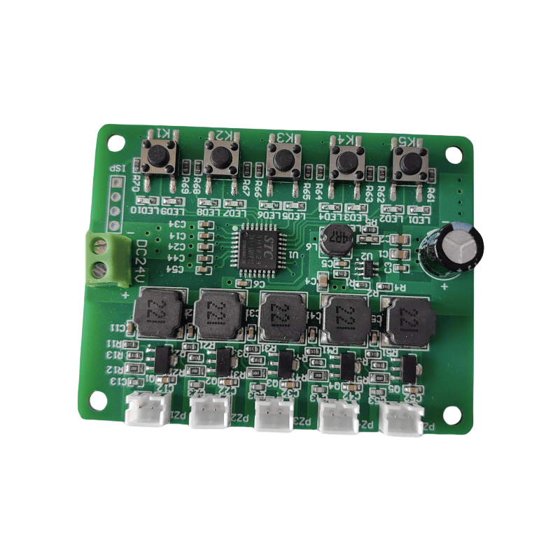
Driver Board For Humidifier Crescent PCB Board Timing 2/4h Function 1.5W
-
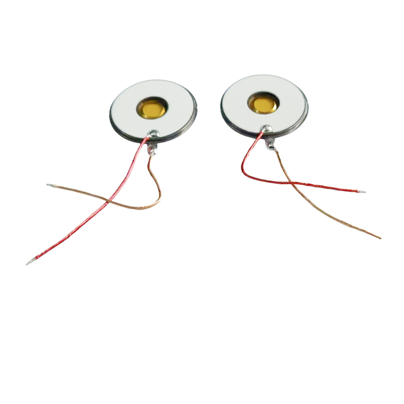
M16-108KHZ Polyimide PI MembraneMesh Micro Mesh NebulizerMedical NebulizerUltrasonic Mesh Nebulizer3μm Microporous Inhalation Nebulizer With Nebulizing DiscPower Consumption1~1.5W
-
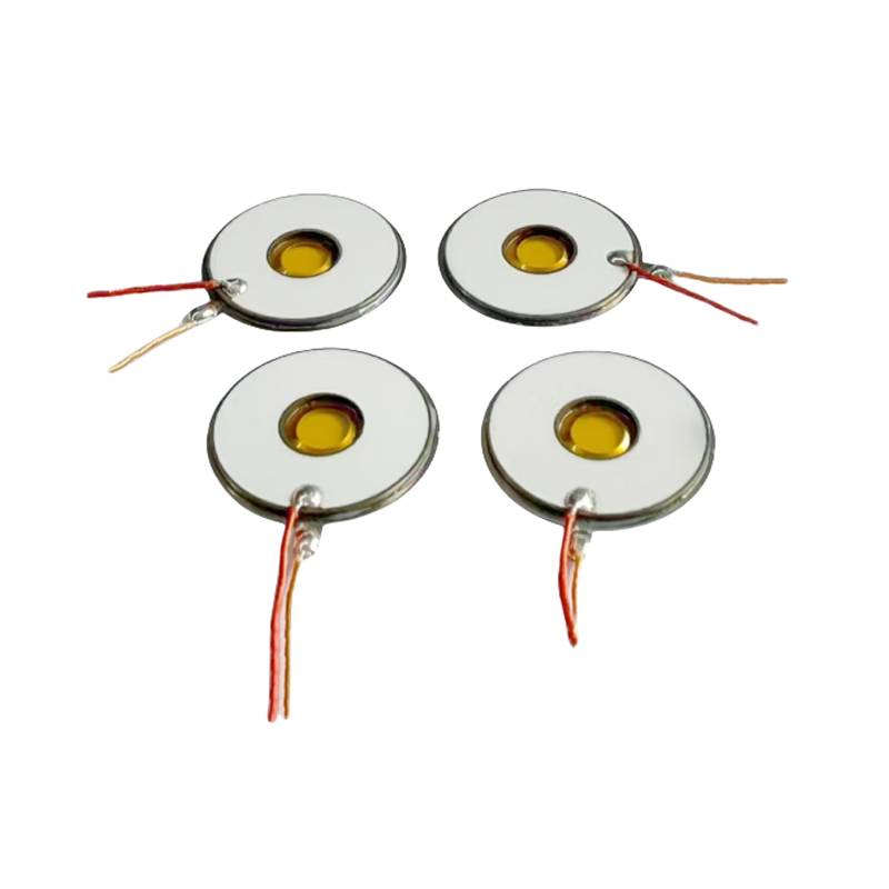
M16-108KHZ Polyimide PI MembraneMesh Micro Mesh NebulizerMedical NebulizerUltrasonic Mesh Nebulizer3μm Microporous Nebulizer Disc For Inhaler Nebulizer
-
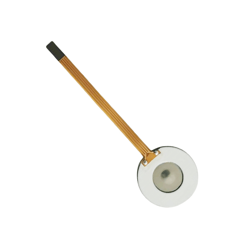
M16-110KHZ Polyimide PI MembraneMesh Micro Mesh NebulizerMedical NebulizerUltrasonic Mesh Nebulizer3μm Microporous Nebulizer Disc For Inhalation Nebulizer
-
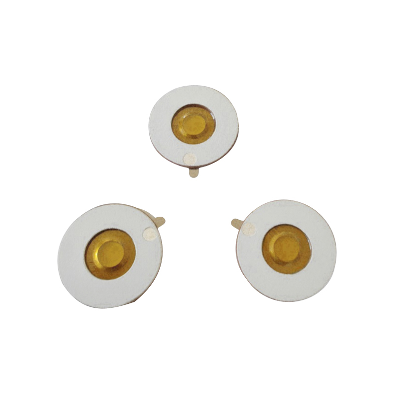
M16-108KHZ Polyimide PI MembraneMesh Micro Mesh NebulizerMedical NebulizerUltrasonic Mesh Nebulizer Tablet3μm Microporous Inhalation Budesonide Nebulizer Tray
- Quick Links
- Product
- About
- Application
- News
- Contact
- Product Links
- Medical Mesh Piezo Atomizer
- Polymer PI Film Piezo Atomizer
- KNN Lead-free Mesh Piezo Atomizer
- PI Lead Free Mesh Zeroing Chip
- Micro-mesh Piezo Atomizer For Heater
- Piezo Atomizer For Fan/Humidification/Beauty
- Ultrasonic Atomizing Transducer
- Ultrasonic High-frequency Piezo Atomizer
- Power Generation/Heating Sensor Piezo Atomizer
- Medical Piezo Atomizer PCB Design
- Precision Laser Micro-hole Processing Technology
- Contact
-
Building 1, Fortune Star 2, No.311 Huanzhen North Road, Chang'an Town, Haining City, Zhejiang Province, China.

-
+86-18006619680

-
+86-13777879680

-
Felix@saidapiezo.com

riney@saidapiezo.com
yugao@saidapiezo.com
emily@saidapiezo.com
dean@saidapiezo.com -
Felix: +86 18157327658

John: +86 18957351358
Emily: +86 18957339358
Dean: +86 15356418868
- Mobile