


 English
 中文简体
What Makes a PCB Medical Piezo Atomizer Disc Reliable? Design, Compliance and Testing
How the Driver Board and Atomizing Disc Work Together
A PCB medical piezo atomizer disc is not a single part but a system. A piezoelectric ceramic element, usually bonded to a thin perforated metal mesh, sits in contact with liquid medication. A printed circuit board supplies the alternating electrical drive that makes the element vibrate fast enough to push liquid through the mesh and form a fine aerosol. Engineers who design nebulizers and respiratory devices need to understand both halves of this system, because a strong disc cannot compensate for a weak driver, and a sophisticated driver cannot rescue a poorly matched disc.
The Piezoelectric Principle in Practical Terms
Piezoelectric ceramics change shape when a voltage is applied across them, and they produce a small electrical charge when they are deformed. In an atomizer, the driver alternates the voltage at high frequency so the ceramic expands and contracts thousands of times per second. That motion moves the mesh, which draws liquid through its holes and breaks it into droplets. Typical mesh designs operate in the ultrasonic range, commonly somewhere between roughly 100 kHz and 180 kHz, with the exact value depending on disc diameter, hole pattern, and the mounting method.
The resulting spray quality depends on more than frequency alone. Amplitude, waveform shape, and the stability of the drive over time all affect droplet size distribution and output rate. A driver that delivers a clean, well-controlled waveform produces a more consistent mist, while a noisy or unstable waveform can cause uneven spray, audible buzzing, and unnecessary heating.
Why the Disc Cannot Work Alone
The ceramic element behaves electrically like a capacitive load with its own resonance characteristic. Its resonant frequency shifts as temperature changes, as the liquid level changes, and as the mesh ages. If the drive frequency stays fixed while the resonance moves, the disc loses efficiency, runs hotter, and may sprays unevenly. The PCB therefore has to generate a clean waveform, track the changing resonance, and limit current so the element never operates beyond its safe range.
Design Factors That Separate Stable Products From Problem Ones
Many field problems in atomizer products trace back to decisions made early in the board design. The factors below are the ones that most often determine whether a unit performs consistently across its operating range and across its service life. None of them is exotic, but each requires deliberate attention during schematic and layout work.
Frequency Tracking and Resonance Shift
Because the disc resonance moves with temperature, liquid loading, and mechanical aging, a fixed-frequency driver can lose efficiency within minutes of operation. Designers typically address this with closed-loop tracking, where the controller reads a feedback signal such as current or phase and adjusts the drive frequency to stay near the resonance peak. Good tracking algorithms also include a search routine for start-up and a recovery routine if the load changes suddenly.
- Resonance moves as liquid level, temperature, and mesh condition change
- A fixed-frequency driver can lose a large share of its efficiency under load drift
- Closed-loop tracking uses feedback to keep the drive close to the resonance peak
- Start-up search and fault recovery routines prevent stalls and overheating
Power Stage and Thermal Margin
The power stage must deliver peak current with headroom, and the components around it must survive worst-case ambient temperature. A common practice is to derate semiconductors, capacitors, and magnetic parts to roughly 60 to 70 percent of their rated limits under the highest expected operating temperature. This margin matters because atomizers often run for long sessions in enclosed spaces, where heat accumulates faster than in open test benches.
Layout Practices That Reduce Noise and Drift
Layout quality affects both electrical performance and electromagnetic behavior. The high-current loop should be as short and tight as possible. Sensing circuits need their own careful ground path so that switching currents do not corrupt the feedback signal. Copper area under power devices helps spread heat, and the matching network should sit close to the disc connector to limit stray inductance.
- Keep the high-current switching loop short and compact
- Join sensing ground and power ground at a single controlled point
- Place the matching network close to the disc connector
- Provide enough copper for heat spreading under power devices
The table below summarizes common design targets and the reason each one matters during validation.
| Design Parameter | Typical Target | Why It Matters |
|---|---|---|
| Drive waveform purity | Low harmonic content | Reduces audible noise and disc heating |
| Current limit margin | At least 30 percent above normal load | Protects the element during overload |
| Operating ambient | Stated range with derating applied | Prevents thermal drift in long sessions |
| Board copper and thickness | Selected for maximum current | Controls temperature rise |
Medical Compliance Expectations for Nebulizer PCBA
A nebulizer is a medical electrical device, so its driver board becomes part of a larger safety and performance case. Design teams usually build their evidence around a family of international standards, and the circuit must be planned for these requirements from the first schematic rather than corrected after prototype testing. A board that is electrically elegant but fails isolation or emissions tests can delay a product launch by many months.
Electrical Safety
Electrical safety work covers leakage current limits, insulation between mains and patient-applied parts, and the spacing of conductors. Creepage and clearance distances depend on working voltage, insulation type, and pollution degree, and they must be verified against the standard that applies to the target market. Designers should also consider fault conditions such as a shorted component or a loose connector, because the standard expects the device to remain safe even when one fault occurs.
Electromagnetic Compatibility
Electromagnetic compatibility testing looks at two things: how much electrical noise the device emits, and how well it tolerates noise from its surroundings. A high-frequency switching driver is a natural noise source, so filtering, careful layout, and sometimes shielding are needed. Engineers often reference IEC 60601-1-2 for medical equipment EMC requirements, and they plan pre-compliance measurements early because late discoveries are expensive.
Materials and Restricted Substances
Restricted substance rules such as RoHS and REACH affect solder alloys, laminates, coatings, and component finishes. Lead-free assembly is now the usual baseline for medical boards, but it introduces higher soldering temperatures that stress the board and parts. Buyers should ask for material declarations and process controls that show how restricted substances are managed through the supply chain.
Selecting a development partner who understands medical nebulizer pcb design requirements from the start can shorten this cycle, because compliance-driven layout choices are much cheaper to make at the schematic stage than during redesign.
| Requirement Area | Commonly Referenced Standard |
|---|---|
| Medical electrical safety | IEC 60601-1 series |
| EMC for medical equipment | IEC 60601-1-2 |
| Restricted substances | RoHS and REACH |
| Quality management | ISO 13485 for medical devices |
Testing Protocols That Expose Weak Designs Early
Testing is where theoretical design margins meet real operating conditions. A well-planned validation program covers electrical behavior, thermal performance, mechanical robustness, and production consistency. The most useful test plans are designed to uncover failures before the product reaches patients, and they produce records that support regulatory submissions and supplier audits.
Electrical Verification
- Measure the impedance of the disc across a frequency sweep to confirm the resonance range
- Check the output waveform for distortion and harmonic content at several load conditions
- Verify current and voltage limits, including behavior during deliberate overload
- Measure standby power and confirm that sleep modes wake reliably
Environmental and Mechanical Stress
Environmental tests typically include temperature cycling, humidity exposure, and long-duration running at the upper end of the rated temperature range. A common approach cycles units between about minus 10 and 50 degrees Celsius for many repetitions, then checks output consistency and solder joint integrity. Portable devices also need drop and vibration testing, since a driver board that survives a bench test may still fail after a fall from a table.
Production Screening
Design validation proves the concept, but production screening keeps every unit consistent. Functional testing at the end of the line should confirm drive output, protection behavior, and basic thermal limits. Sampling-based burn-in helps reveal early failures, and traceability records tie each board to its component lots and process steps. These records become critical when a field issue must be investigated.
Application Scenarios and Their Design Priorities
The right driver design depends heavily on how the atomizer will be used. A handheld unit running on a battery has different priorities from a clinical humidifier that operates continuously on mains power. Matching the design priorities to the application early prevents over-engineering in some areas and dangerous shortfalls in others.
| Application | Main Design Priority | Typical Drive Focus |
|---|---|---|
| Handheld medical nebulizer | Battery efficiency and low noise | Adaptive frequency and sleep modes |
| Head-mounted portable unit | Weight and thermal comfort | Compact layout and low surface temperature |
| Clinical humidifier | Continuous duty reliability | Thermal margin and water safety |
| Connected respiratory device | Data logging and connectivity | Isolated control interfaces |
In a battery-powered device, every milliwatt of standby consumption matters, so the driver should enter a low-power state quickly when no therapy is running. In a head-mounted design, the board must fit a tight envelope and keep its outer surfaces at a temperature that is comfortable against the skin. Continuous-duty humidifiers prioritize thermal derating and protection against water ingress, since their operating hours are long and their environment is often humid.
Preparing a Request for Quotation Without Delays
Clear technical requirements shorten the path from first contact to a usable sample. Many delays come from missing information that forces repeated rounds of clarification. A well-prepared request lets a supplier estimate effort, identify the right test resources, and propose a realistic development schedule.
- Disc diameter, mesh hole pattern, and expected resonance range
- Supply voltage, battery chemistry, and power budget
- Number of drive channels and any timing or sequencing requirements
- Target certifications and destination markets
- Expected quantities for prototype samples and for volume production
Questions Worth Asking a Prospective Supplier
Beyond price and lead time, buyers should ask how a supplier validates frequency tracking, what test records accompany each batch, and how design changes are controlled after release. Those answers reveal whether the supplier has the engineering depth to support a medical product over its full life. Buyers planning a custom pcb design for piezo atomizer disc should also confirm who owns the firmware, how source files are protected, and what documentation is included for regulatory submissions.
Frequently Asked Questions
Q1: What is a PCB medical piezo atomizer disc?
It is a complete atomizing system that combines a piezoelectric ceramic element, usually with a perforated mesh, and a driver circuit board. The board generates the high-frequency drive signal that makes the element vibrate and produce a fine aerosol for medical inhalation.
Q2: Why does a piezo atomizer disc need a driver board?
The ceramic element cannot produce its own alternating drive signal. The driver supplies a controlled waveform at the correct frequency, tracks the resonance as conditions change, and limits current so the element and the device stay within safe operating limits.
Q3: What standards usually apply to nebulizer driver boards?
Most designs reference the IEC 60601 series for medical electrical safety and EMC, along with RoHS and REACH for restricted substances. Manufacturers working under a medical quality system often follow ISO 13485 for their development and production processes.
Q4: Can a driver board be customized for a specific disc and application?
Yes. Customization usually covers the drive frequency range, channel count, voltage input, timing functions, and protection behavior. Firmware features such as resonance tracking, sensing, or connectivity can also be adapted to the target product.
Q5: What information should be included in a quotation request?
A useful request includes disc size and resonance range, supply voltage, number of channels, target certifications, application type, and expected sample and production quantities. Clear information allows the supplier to estimate development effort and respond with a realistic schedule.
Related Products
-
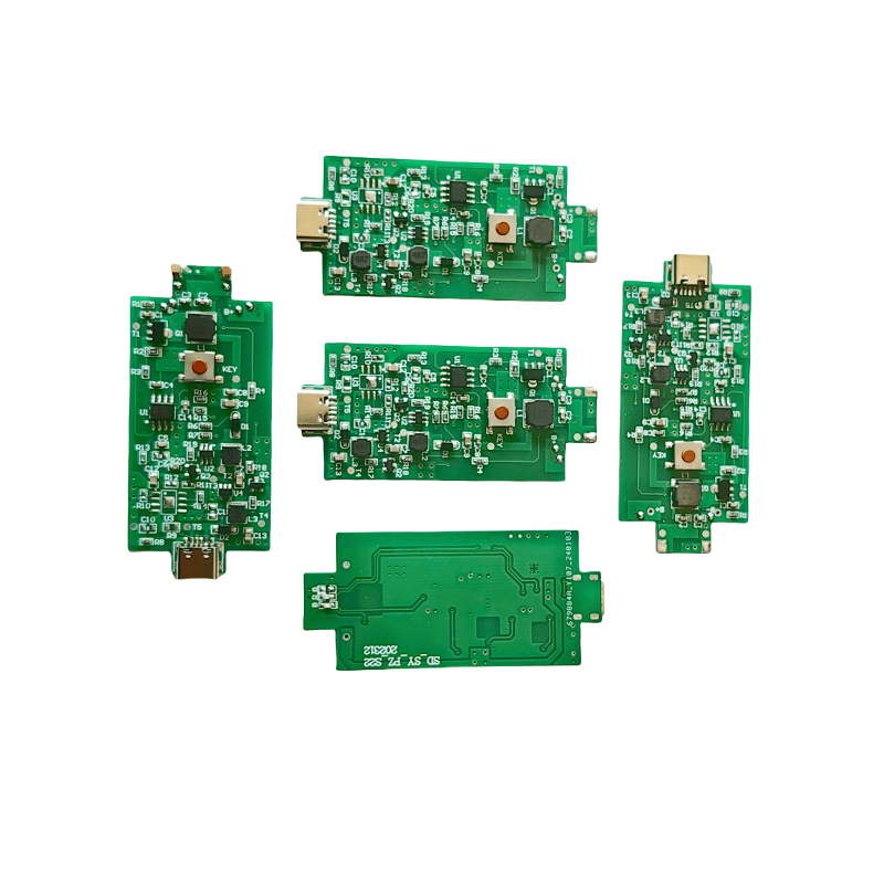
Humidifier Aromatherapy Humidifier Misting Tray PCB Board USB6V12V24V Five Head PCB Driver Board 10 Head Driver Board
-
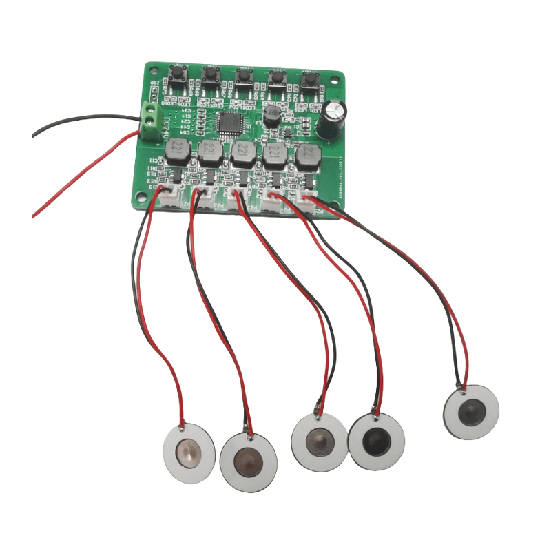
Medical Inhalation Nebulizer Respirator Head-mounted Nebulizer PCB Driver B
-
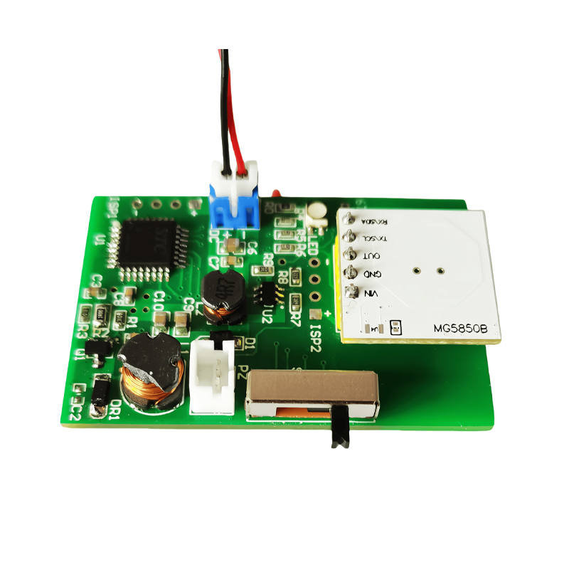
Medical Mesh Atomizer Tray PCB Electronic Smoking Cessation Atomizer PCB Driver Board
-
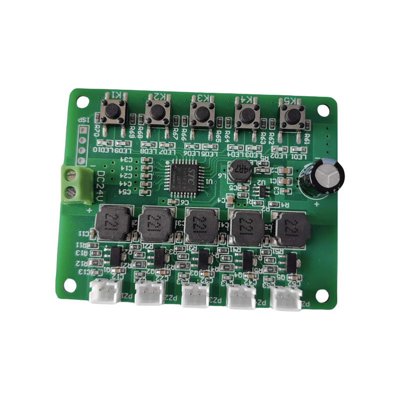
Driver Board For Humidifier Crescent PCB Board Timing 2/4h Function 1.5W
-
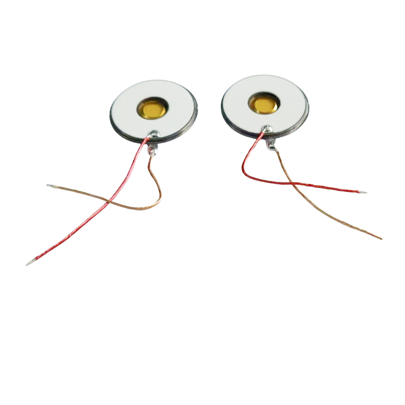
M16-108KHZ Polyimide PI MembraneMesh Micro Mesh NebulizerMedical NebulizerUltrasonic Mesh Nebulizer3μm Microporous Inhalation Nebulizer With Nebulizing DiscPower Consumption1~1.5W
-
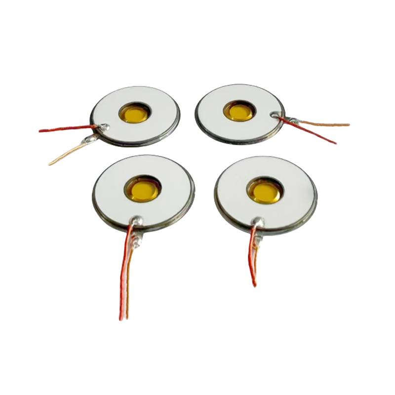
M16-108KHZ Polyimide PI MembraneMesh Micro Mesh NebulizerMedical NebulizerUltrasonic Mesh Nebulizer3μm Microporous Nebulizer Disc For Inhaler Nebulizer
-
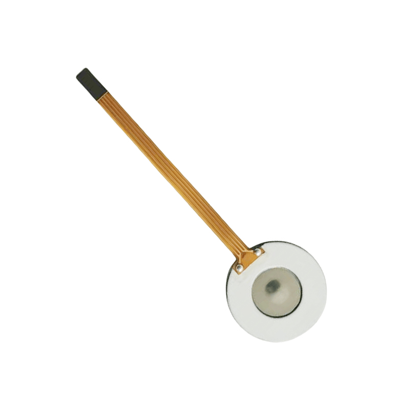
M16-110KHZ Polyimide PI MembraneMesh Micro Mesh NebulizerMedical NebulizerUltrasonic Mesh Nebulizer3μm Microporous Nebulizer Disc For Inhalation Nebulizer
-
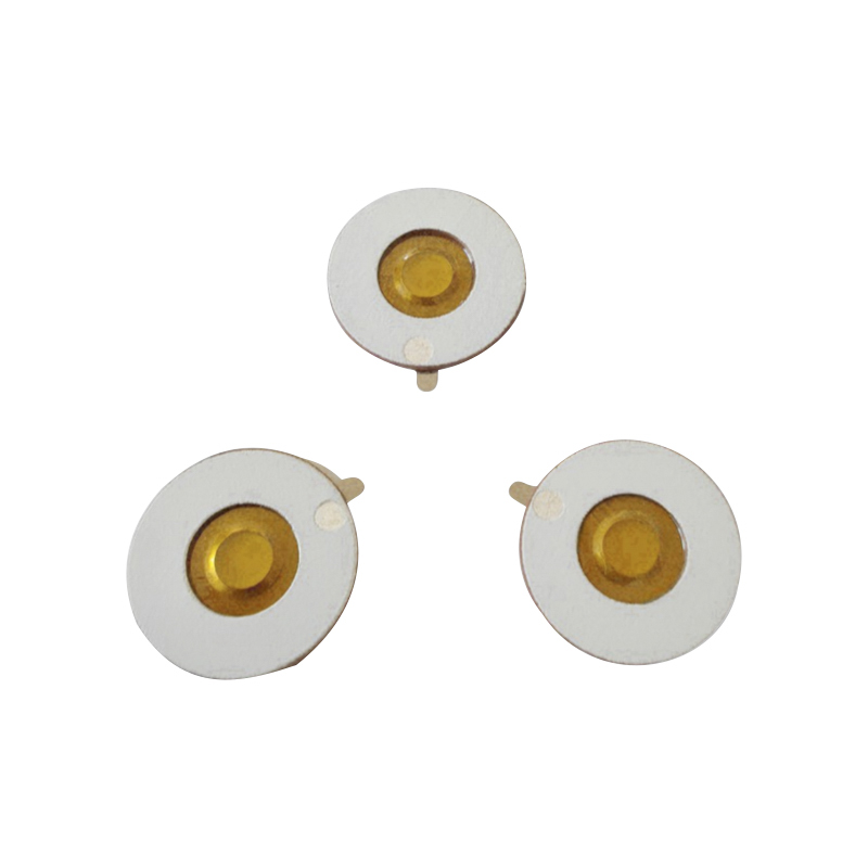
M16-108KHZ Polyimide PI MembraneMesh Micro Mesh NebulizerMedical NebulizerUltrasonic Mesh Nebulizer Tablet3μm Microporous Inhalation Budesonide Nebulizer Tray
- Quick Links
- Product
- About
- Application
- News
- Contact
- Product Links
- Medical Mesh Piezo Atomizer
- Polymer PI Film Piezo Atomizer
- KNN Lead-free Mesh Piezo Atomizer
- PI Lead Free Mesh Zeroing Chip
- Micro-mesh Piezo Atomizer For Heater
- Piezo Atomizer For Fan/Humidification/Beauty
- Ultrasonic Atomizing Transducer
- Ultrasonic High-frequency Piezo Atomizer
- Power Generation/Heating Sensor Piezo Atomizer
- Medical Piezo Atomizer PCB Design
- Precision Laser Micro-hole Processing Technology
- Contact
-
Building 1, Fortune Star 2, No.311 Huanzhen North Road, Chang'an Town, Haining City, Zhejiang Province, China.

-
+86-18006619680

-
+86-13777879680

-
Felix@saidapiezo.com

riney@saidapiezo.com
yugao@saidapiezo.com
emily@saidapiezo.com
dean@saidapiezo.com -
Felix: +86 18157327658

John: +86 18957351358
Emily: +86 18957339358
Dean: +86 15356418868
- Mobile