


 English
 中文简体
中文简体What Makes Precision Laser Microvias Decisive for Piezo Atomizer Mesh Performance?
Where Micro-Hole Accuracy Decides Mist Quality
A piezoelectric atomizer turns electrical energy into a fine spray by vibrating a thin metal mesh at high frequency. The character of the mist depends almost entirely on the geometry of the holes the liquid passes through. When engineers review a new mesh design, they are really asking how accurately each micro-hole can be formed, how consistently it can be repeated, and whether it will hold its limits across thousands of pieces. This is why precision laser microvias have become a common route for manufacturers of medical nebulizers, beauty instruments, humidifiers, and aroma diffusers.
Two mesh plates can look identical under a desk lamp and still produce very different results. One may generate a dense cloud of small droplets, while the other produces larger drops that cling to the surface and reduce output. Hole diameter, hole depth, taper, and spacing all influence how liquid is pushed through the plate and how each droplet detaches. Small deviations in any of these values appear as uneven mist density, inconsistent heating inside the device, and complaints from users who notice that the spray changes from one unit to the next.
Traditional mechanical drilling and chemical etching both struggle at this scale. Drill bits wear quickly when the diameter falls below a few tens of micrometers, and burrs formed during drilling can disturb the flow path. Etching can be uniform across a plate, but it offers limited control over the profile of each individual hole. Laser processing avoids much of this difficulty because energy is delivered without physical contact, so thin foils do not bend under cutting force and each hole can be formed in a planned sequence.
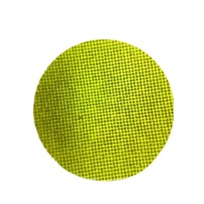
Key takeaway: mist quality follows hole geometry, and that geometry must be controlled at the micrometer level rather than the millimeter level common in general machining.
How Hole Geometry Shapes Droplet Behavior
Straight Holes Versus Tapered Holes
Two profile types dominate atomizer mesh design. Straight holes keep a constant diameter from the liquid side to the spray side. They are simple to model and inspect, and when the diameter is held tightly they produce a predictable droplet size. Tapered holes widen toward the spray side, forming a shallow cone. The taper reduces resistance as liquid enters, and it can help each droplet release cleanly from the outlet, which many designers prefer for continuous fine mist.
The table below summarizes the trade-offs that engineering teams usually weigh when choosing between the two profiles.
| Feature | Straight hole | Tapered hole |
|---|---|---|
| Typical use | Fixed-volume spray | Continuous fine mist |
| Flow resistance | Higher at the inlet | Lower at the inlet |
| Inspection | Gauge-based diameter check | Profile and angle check |
| Main risk | Edge burrs affect flow | Taper angle drift |
Neither profile is universally better. The right choice depends on the viscosity of the liquid, the target droplet range, and the drive frequency of the transducer. A design review should state those three inputs first, because they determine whether the problem can be solved by diameter alone or needs a full profile specification with angle and tolerance.
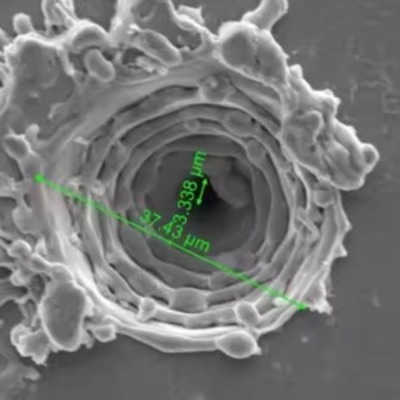
Process Route From Sheet Metal to Finished Mesh
A reliable process route is built from steps that each protect the next one. Skipping a stage or changing the sequence can shift the final hole profile even when the laser settings look correct on paper. A typical route for a laser-formed mesh plate includes the following stages.
- Foil preparation: flatten and clean the metal sheet, verify thickness within the agreed range, and mark reference edges for alignment.
- Fixturing: clamp the foil on a flat stage so the hole pattern aligns with the mounting features of the finished part.
- Laser hole formation: form each hole with short pulses in a controlled scan order, adjusting spot size and energy for the target geometry.
- Edge cleaning: remove recast material and micro-burrs with a step that does not change the hole diameter.
- Final inspection and packing: measure sampled plates, record results, and protect finished mesh from scratches and contamination.
Scan order deserves particular attention. If the laser moves across the plate in one direction without interruption, heat accumulates on one side and holes at the far edge can drift from the target. Alternating scan direction and inserting short cooling intervals spreads the thermal load evenly, which keeps the diameter spread narrow across the full active area.
Measurable Targets for Holes, Spacing, and Flatness
Specifications should be written so that a supplier can measure them on the production floor. Phrases such as high precision give a purchasing team nothing to compare. A practical specification lists each characteristic, its target range, and the method used to verify it.
| Characteristic | Typical target | Verification method |
|---|---|---|
| Hole diameter | 2 to 30 micrometers | Optical gauge sampling |
| Diameter tolerance | Within 1 micrometer in critical zones | Microscope measurement |
| Hole count per piece | Hundreds to several thousand, as drawn | Image analysis |
| Pitch uniformity | Consistent across the active area | Coordinate measurement |
| Plate flatness | Limited deviation across the mesh | Surface profile check |
| Edge burr height | Only a few micrometers | Cross-section inspection |
Measurement planning matters as much as the target itself. Sampling should cover the center and the edges of each plate, because processing heat can produce small gradients across the surface. A plan that checks only one zone may approve parts that later fail in service.
In one anonymized pilot, holes measured at the plate center stayed well within tolerance, while holes near the outer edge drifted by about 2 micrometers. Changing the scan order and adding cooling intervals closed the gap in the following batch, and edge measurements matched the center within the agreed limit.
Laser Parameters That Control Edge Quality
Pulse Width and Energy Control
Short pulses limit the spread of heat into the surrounding metal, which reduces the recast layer that forms around each hole. Longer pulses remove material faster, but they can leave thicker edges that narrow the flow path and change droplet behavior. Energy per pulse should remove material cleanly without creating a heat-affected band wider than the design allows.
Spot Overlap and Scan Strategy
Overlap between successive pulses determines how smoothly the wall of each hole forms. Too little overlap leaves a ridged profile, while excessive overlap wastes time and adds heat. Many teams use a short multi-pass strategy: a rough pass forms the hole, and a finishing pass at lower energy refines the wall and removes residual edge material.
Assist Gas and Debris Removal
Assist gas clears molten debris from the hole during formation. Its direction, pressure, and cleanliness all affect the result.
- Gas flow should push debris away from the exit side so particles do not re-settle inside the hole.
- Pressure must be balanced, because excessive force can vibrate a thin foil and shift the pattern.
- Filtration keeps re-deposited particles away from the next target area during long production runs.
Edge quality is rarely fixed by one parameter. It is the combined result of pulse energy, overlap, scan order, and gas flow.
Common Defects and How to Catch Them Early
Most defects in laser-formed mesh trace back to a small number of causes. Recognizing the symptom early makes it far easier to correct the process before a full batch is affected.
- Partially clogged holes: usually caused by re-deposited debris. Transmitted light sampling reveals the problem quickly.
- Taper drift: often caused by focus shift after long runs. Checking focus at fixed intervals keeps the profile stable.
- Exit-side burrs: commonly linked to low gas flow or worn fixtures. A cross-section check confirms the cause.
- Diameter spread across the plate: generally caused by thermal drift. Sampling at the center and edges identifies the trend.
A real example shows how these checks pay off. A buyer once reported that about 18 plates out of every 1,000 failed a flow test. Root cause analysis pointed to a gas nozzle that had shifted slightly during a fixture change. The supplier added an alignment check at the start of every shift, and within two weeks the failure rate dropped below 2 plates out of every 1,000.
Verification Methods That Build Buyer Confidence
Optical and Electron Microscopy
Optical microscopy is fast enough for routine sampling and works well for diameter and pitch checks. Electron microscopy offers much higher magnification and reveals wall structure, recast layers, and micro-cracks that optical methods can miss. A balanced plan uses optical checks for daily production and electron imaging for qualification and failure analysis.
Functional Flow and Spray Testing
Dimensional data proves that holes are the right size, but it does not prove the mesh will perform. Functional testing measures flow rate, spray pattern, and droplet distribution in a fixture that mimics the final device. Comparing these results with the dimensional report shows whether the specification captures the properties that matter in use.
A dimensional report proves the holes are the right size, while a spray test proves the mesh works.
Choosing Mesh Materials for Reliable Atomizing
Material selection shapes both laser behavior and long-term mesh performance. Each metal family responds differently to heat and has its own corrosion profile.
Austenitic stainless steel offers good corrosion resistance and stable mechanical behavior, which makes it a common choice for devices that contact water-based solutions. It forms clean hole walls but requires careful heat control to limit recast layers.
Nickel-based alloys provide strong fatigue resistance under continuous vibration. They suit demanding applications where the plate must keep its shape over a long service life, although cost is higher and processing windows are narrower.
Coated foils add a surface layer for chemical compatibility or wetting control. The coating must survive laser processing without cracking, so coating type and laser parameters should be qualified together.
Foil thickness is another key decision. Thinner foils pierce more cleanly but deform more easily during handling and fixturing. Thicker foils hold their shape but demand longer cycle times and tighter taper control. Matching thickness to the target hole profile is usually the most effective way to balance yield against cycle time.
Sourcing Checklist for Buyers
Technical capability is easier to judge when a buyer knows which questions to ask. The checklist below helps purchasing and engineering teams compare suppliers on evidence rather than brochure claims.
- Confirm the minimum achievable hole size using sample pieces, not only published figures.
- Request a measurement report showing the actual diameter distribution across the plate.
- Ask how focus, gas flow, and fixture alignment are monitored during production.
- Review the process route, especially edge cleaning and final inspection.
- Agree on the sampling plan and acceptance criteria in writing before the first order.
- Start with a pilot batch before moving to bulk volumes.
Suppliers who explain each of these points in plain terms usually run a more disciplined process. For a technical overview of the same process, review the related laser microvias for atomizer mesh page, which describes the working range and how it is measured.
Frequently Asked Questions
Q1: What hole sizes are practical for atomizer mesh?
Many atomizer designs use holes between about 2 and 30 micrometers. The best choice depends on the liquid, the desired droplet range, and the transducer frequency, so the target should be confirmed with a sample before the design is frozen.
Q2: How does laser processing compare with chemical etching for thin foils?
Etching offers good uniformity across a plate but limited control over individual hole profiles. Laser processing forms each hole in a planned sequence with defined taper and edge quality, which matters when the profile itself is part of the specification.
Q3: How can hole geometry be verified without destroying a sample?
Optical microscopy and transmitted light sampling check diameter, pitch, and blockage without cutting the part. For taper and wall structure, a witness piece processed with the same parameters can be sectioned while production parts remain intact.
Q4: What information should a quotation request include?
Include the foil material and thickness, the hole layout drawing, the target diameter range, the profile type, the active area size, the sampling expectations, and expected quantities for pilot and bulk orders. Clear inputs reduce revision cycles and make the quotation more accurate.
Q5: Why does the first batch sometimes take longer?
The first batch usually includes parameter tuning, fixture verification, and inspection calibration. Once the process is stable, later batches move faster, which is why many buyers treat the pilot run as a qualification step.
Turning Specifications Into Stable Mist Output
Stable mist output begins long before the device is assembled. It starts with a clearly defined hole geometry, a process route that protects each stage, and measurement methods that reflect how the mesh will actually be used. When these elements line up, the plate delivers the same spray from the first unit to the last.
For teams planning a new atomizer design, the most useful next step is a written specification and a sample run. Work through the hole profile, material, and verification plan together, and use the micro-hole processing reference to compare process limits before setting final targets.
Related Products
-
Humidifier Aromatherapy Humidifier Misting Tray PCB Board USB6V12V24V Five Head PCB Driver Board 10 Head Driver Board
-
Medical Inhalation Nebulizer Respirator Head-mounted Nebulizer PCB Driver B
-
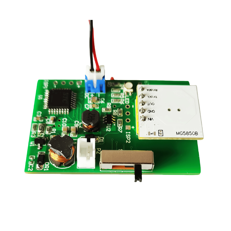
Medical Mesh Atomizer Tray PCB Electronic Smoking Cessation Atomizer PCB Driver Board
-
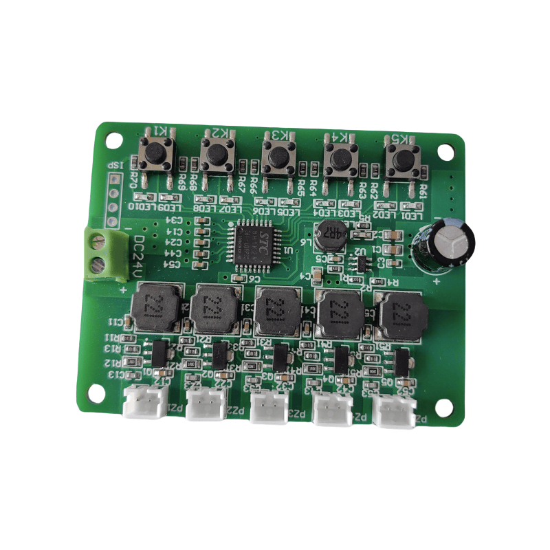
Driver Board For Humidifier Crescent PCB Board Timing 2/4h Function 1.5W
-
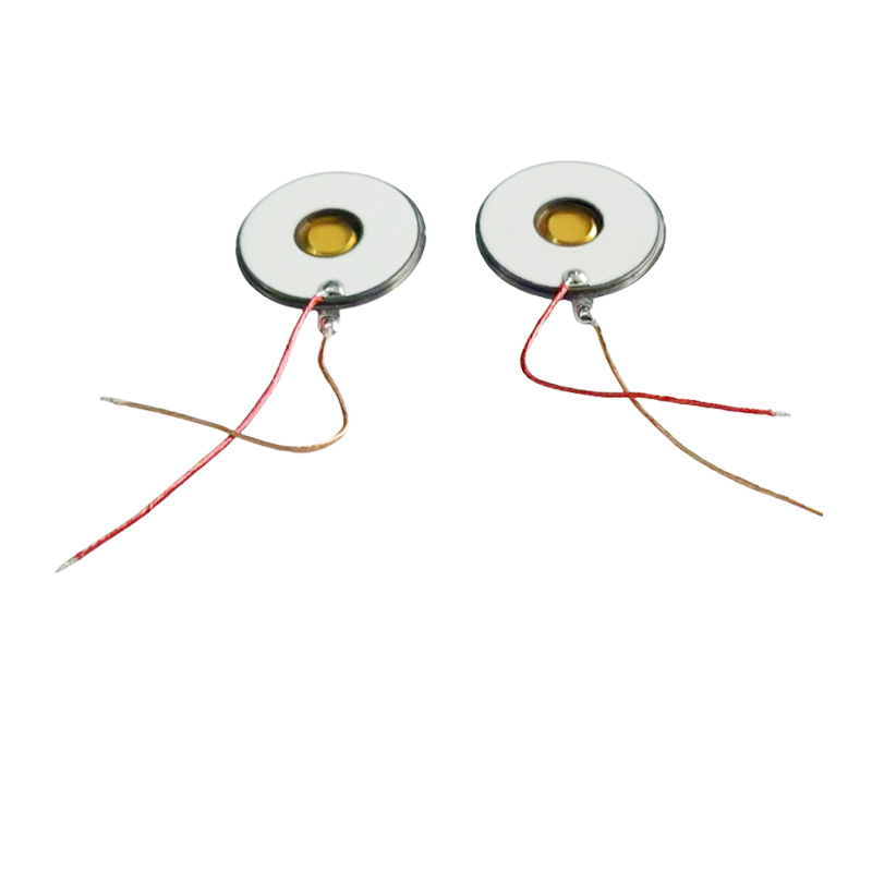
M16-108KHZ Polyimide PI MembraneMesh Micro Mesh NebulizerMedical NebulizerUltrasonic Mesh Nebulizer3μm Microporous Inhalation Nebulizer With Nebulizing DiscPower Consumption1~1.5W
-
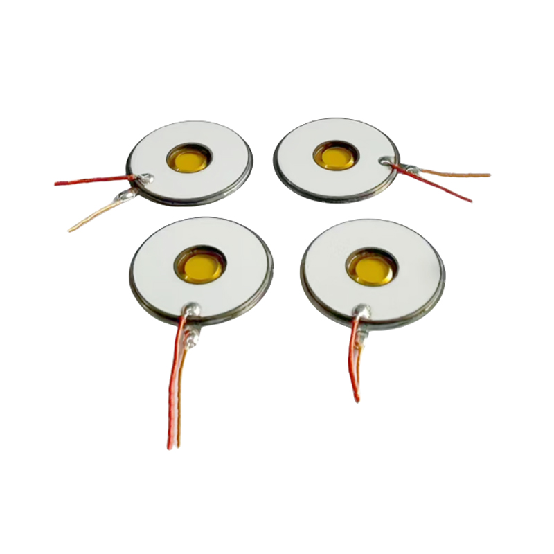
M16-108KHZ Polyimide PI MembraneMesh Micro Mesh NebulizerMedical NebulizerUltrasonic Mesh Nebulizer3μm Microporous Nebulizer Disc For Inhaler Nebulizer
-
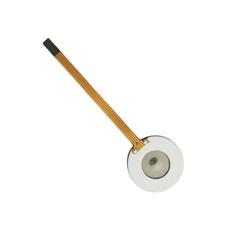
M16-110KHZ Polyimide PI MembraneMesh Micro Mesh NebulizerMedical NebulizerUltrasonic Mesh Nebulizer3μm Microporous Nebulizer Disc For Inhalation Nebulizer
-
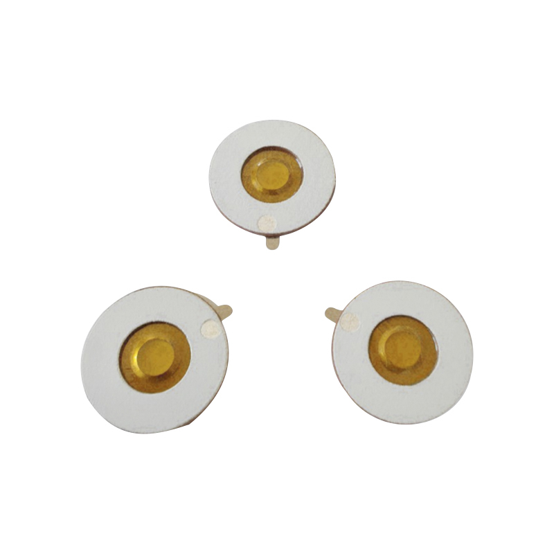
M16-108KHZ Polyimide PI MembraneMesh Micro Mesh NebulizerMedical NebulizerUltrasonic Mesh Nebulizer Tablet3μm Microporous Inhalation Budesonide Nebulizer Tray
- Quick Links
- Product
- About
- Application
- News
- Contact
- Product Links
- Medical Mesh Piezo Atomizer
- Polymer PI Film Piezo Atomizer
- KNN Lead-free Mesh Piezo Atomizer
- PI Lead Free Mesh Zeroing Chip
- Micro-mesh Piezo Atomizer For Heater
- Piezo Atomizer For Fan/Humidification/Beauty
- Ultrasonic Atomizing Transducer
- Ultrasonic High-frequency Piezo Atomizer
- Power Generation/Heating Sensor Piezo Atomizer
- Medical Piezo Atomizer PCB Design
- Precision Laser Micro-hole Processing Technology
- Contact
-
Building 1, Fortune Star 2, No.311 Huanzhen North Road, Chang'an Town, Haining City, Zhejiang Province, China.

-
+86-18006619680

-
+86-13777879680

-
Felix@saidapiezo.com

riney@saidapiezo.com
yugao@saidapiezo.com
emily@saidapiezo.com
dean@saidapiezo.com -
Felix: +86 18157327658

John: +86 18957351358
Emily: +86 18957339358
Dean: +86 15356418868
- Mobile